Motor Commands
These commands effect the operation of the motor in some way. Typically (unless otherwise mentioned), they are represented by data structures that are placed in a command queue (see queue parameter). They occupy a length in bytes and will only be added to the queue if there is sufficient room. A command is evaluated when it is at the head of the Execution Queue (Queue 0). Once a command is evaluated, it is popped off the Execution Queue and the next command is then evaluated. If the Execution Queue queue is empty, the queue remains idle and the no new commands are evaluated until they are placed in the queue.
Some commands have preconditions prior to execution (ex. GoTo requires motor must not be in a BUSY state). If the preconditions are not met, the command is not evaluated until they are met. In some circumstances it is possible to enter a dead-locked state. For example if a Run command is executed (which maintains a constant speed) followed by a StepClock command (which has the precondition that the motor is stopped), the Execution Queue will enter a dead-locked state. The system will wait patiently for a precondition that will never be met. Issuing an EStop or a EmptyQueue command will exit this dead-locked state. It is up to the programmer to understand the preconditions and never issue commands that would dead-lock the Execution Queue.
The EStop (Emergency Stop) is special in that it is not associated with a queue and does not have any preconditions. When issued, this command immediately stops evaluation of the Execution Queue to halt the motor according to the parameters given. Once evaluated, the Execution Queue is cleared and will remain idle until new commands are issued.
For more information on the Execution Queue and the Command Queues in general, see the Command Queue page.
Each command has an associated target parameter (default 0). This parameter is used when Daisy Chaining is enabled to route the command to the target motor over the high speed serial bus. See Daisy Chain for more information.
Table of contents
- Registers
- Commands
- Configuration
- Common Config
- Current Mode Only Config
- KT Hold (Current Mode)
- KT Run (Current Mode)
- KT Acceleration (Current Mode)
- KT Deceleration (Current Mode)
- Switch Period (Current Mode)
- Current Prediction Compensation Enabled (Current Mode)
- Minimum On Time (Current Mode)
- Minimum Off Time (Current Mode)
- Fast Decay Time (Current Mode)
- Fast Decay Step Time (Current Mode)
- Voltage Mode Only Config
- KT Hold (Voltage Mode)
- KT Run (Voltage Mode)
- KT Acceleration (Voltage Mode)
- KT Deceleration (Voltage Mode)
- PWM Frequency (Voltage Mode)
- Stall Threshold (Voltage Mode)
- Voltage Supply Compensation Enabled (Voltage Mode)
- Back EMF Low Slope Compensation (Voltage Mode)
- Back EMF Slope Changeover Speed (Voltage Mode)
- Back EMF High Slope Acceleration Compensation (Voltage Mode)
- Back EMF High Slope Deceleration Compensation (Voltage Mode)
Registers
Pos
The Pos register is updated whenever the motor shaft moves and keeps track of the current microstep. It is a 22-bit signed integer ranging from (-2^21 to +2^21 - 1) and will overflow/underflow without errors. On power cycle, this register is reset to zero (Home position).
The Pos register is readable through the motor state interface. Set this register using the SetPos and ResetPos commands.
Mark
The Mark register is used to mark a certain position of the motor shaft.
The Mark register is readable through the motor state interface. Utilize this register with the SetMark and ResetPos commands. Additionally, GoUntil and ReleaseSW commands may act on this register.
Busy
The BUSY flag is used to synchronize motor motions. Depending on the command, the BUSY flag will be asserted until the shaft has reached some speed or position. Read this value through the motor state interface or use the WaitBusy command to delay Command Queue execution.
Commands
EStop (Emergency Stop)
This command is intended to safe the motor during an emergency stop operation or to shut down the motor down when it is no longer needed. This command is similar to the Stop command except it is evaluated immediately when issued and clears the Execution Queue upon completion.
| Parameter | Type | Description | Default |
|---|---|---|---|
| hiz | Bool | Disable the motor bridges (put in High-Impedance state) when stopped. When false, motor bridges will remain active. | true |
| soft | Bool | Use deceleration phase to stop motor. When false, motor will perform a Hard Stop (stops motor immediately). | true |
| target | Int | When Daisy Chain enabled, issue this command to the target motor. | 0 |
- Preconditions: None, this command will be evaluated immediately when issued.
- Effect on BUSY flag: Asserts BUSY flag until motor is stopped.
- Bytes allocated in Queue: This command does not allocate any bytes and cannot be assigned to a queue.
- Side Effects: The Execution Queue is emptied and will remain idle until new commands are issued.
GoHome
This command is equivalent to GoTo(pos=0) with the direction being the minimum path to the Home position.
| Parameter | Type | Description | Default |
|---|---|---|---|
| target | Int | When Daisy Chain enabled, issue this command to the target motor. | 0 |
| queue | Int | The Queue to add this command to | 0 |
- Preconditions: The BUSY flag must not be asserted.
- Effect on BUSY flag: Asserts BUSY flag until home position is reached.
- Bytes allocated in Queue: 5 Bytes.
- Side Effects: None.
GoMark
This command is equivalent to GoTo(pos=MARK) with the direction being the minimum path to the configured MARK
| Parameter | Type | Description | Default |
|---|---|---|---|
| target | Int | When Daisy Chain enabled, issue this command to the target motor. | 0 |
| queue | Int | The Queue to add this command to. | 0 |
- Preconditions: The BUSY flag must not be asserted.
- Effect on BUSY flag: Asserts BUSY flag until mark position is reached.
- Bytes allocated in Queue: 5 Bytes.
- Side Effects: None.
GoTo
Rotates the motor shaft to the specified position in microsteps (see microstep config) relative to Home position (zero position) and holds with active bridges. Observes acceleration, deceleration, and max speed settings and manages motor power according to KTvals in the appropriate phase of operation. When dir parameter is specified, the motor will only rotate according to that parameter. If pos is behind the current position, the shaft will spin until the Pos register overflows/underflows and then reaches desired position.
The Quick Start guide utilizes this command in the Servo Control profile to rotate and hold the position of the shaft.
| Parameter | Type | Description | Default |
|---|---|---|---|
| pos | Int | The position to rotate the shaft (in microsteps) relative to the Home position. Can be positive or negative. | (required) |
| dir | Enum(forward, reverse) | The direction to spin | auto |
| target | Int | When Daisy Chain enabled, issue this command to the target motor. | 0 |
| queue | Int | The Queue to add this command to. | 0 |
- Preconditions: The BUSY flag must not be asserted.
- Effect on BUSY flag: Asserts BUSY flag until specified position is reached.
- Bytes allocated in Queue: 11 Bytes.
- Side Effects: None.
GoUntil
Rotates the motor shaft at the specified steps per second until the external switch (SW pin) is closed (shorted to ground). When switch is closed, the motor performs a Stop(hiz=false,soft=true) command and the specified action is performed. Observes acceleration, deceleration, min speed, and max speed limits. Motor power is managed according to KTvals in the appropriate phase of operation.
The specified action param must be one of the following:
- RESET: Pos register is set to zero (Home position)
- COPYMARK: The current microstep position is copied into the Mark register.
Note: This command is useful during homing and can be coupled with WaitBusy then ReleaseSW for more accuracy.
| Parameter | Type | Description | Default |
|---|---|---|---|
| action | Enum(reset, copymark) | The action to perform when switch is closed. | (required) |
| dir | Enum(forward, reverse) | The direction to spin | (required) |
| stepss | Float | The number of full steps per second to rotate (doesn’t depend on microstep config). This is a decimal parameter so specifying fractional steps per second is allowed. | (required) |
| target | Int | When Daisy Chain enabled, issue this command to the target motor. | 0 |
| queue | Int | The Queue to add this command to. | 0 |
- Preconditions: None.
- Effect on BUSY flag: Asserts BUSY flag until the switch is closed.
- Bytes allocated in Queue: 11 Bytes.
- Side Effects: None.
IncSignal
Increments signal register by the specified value. If value is negative, it is effectively subtracted. See SetSignal and the command queue documentation for more information.
| Parameter | Type | Description | Default |
|---|---|---|---|
| value | Int | The value to increment the signal register. Can be negative. | 1 |
| target | Int | When Daisy Chain enabled, issue this command to the target motor. | 0 |
| queue | Int | The Queue to add this command to. | 0 |
- Preconditions: None.
- Effect on BUSY flag: None.
- Bytes allocated in Queue: 9 Bytes.
- Side Effects: The signal register is incremented by the
valueparam.
Move
Moves the shaft the given number of microsteps in the given direction from the current position.
| Parameter | Type | Description | Default |
|---|---|---|---|
| dir | Enum(forward, reverse) | The direction to spin | (required) |
| microsteps | Int | Number of microsteps to move | (required) |
| target | Int | When Daisy Chain enabled, issue this command to the target motor. | 0 |
| queue | Int | The Queue to add this command to. | 0 |
- Preconditions: The motor is stopped.
- Effect on BUSY flag: Asserts BUSY flag until number of microsteps has been reached.
- Bytes allocated in Queue: 10 Bytes.
- Side Effects: None.
ReleaseSW
Rotates the motor shaft at the minimum speed configuration setting while the external switch (SW pin) is closed (shorted to ground). When switch is opened, the motor performs a Stop(hiz=false,soft=false) (hard stop) command and the specified action is performed. Motor power is managed according to KTvals.
The specified action param must be one of the following:
- RESET: Pos register is set to zero (Home position)
- COPYMARK: The current microstep position is copied into the Mark register.
Note: This command is intended for use during a homing operation. See GoUntil for more information.
| Parameter | Type | Description | Default |
|---|---|---|---|
| action | Enum(reset, copymark) | The action to perform when switch is closed. | (required) |
| dir | Enum(forward, reverse) | The direction to spin | (required) |
| target | Int | When Daisy Chain enabled, issue this command to the target motor. | 0 |
| queue | Int | The Queue to add this command to. | 0 |
- Preconditions: None.
- Effect on BUSY flag: Asserts BUSY flag until the switch is closed.
- Bytes allocated in Queue: 7 Bytes.
- Side Effects: None.
ResetPos
Set the Pos register to zero. This has the effect of making the current shaft position the Home position.
| Parameter | Type | Description | Default |
|---|---|---|---|
| target | Int | When Daisy Chain enabled, issue this command to the target motor. | 0 |
| queue | Int | The Queue to add this command to. | 0 |
- Preconditions: None.
- Effect on BUSY flag: None.
- Bytes allocated in Queue: 5 Bytes.
- Side Effects: The Pos register is set to zero.
Run
Rotates the motor shaft at the specified steps per second. Observes acceleration, deceleration, and max speed limits. Motor power is managed according to KTvals in the appropriate phase of operation.
The Quick Start guide utilizes this command in the Speed Control profile.
| Parameter | Type | Description | Default |
|---|---|---|---|
| dir | Enum(forward, reverse) | The direction to spin | (required) |
| stepss | Float | The number of full steps per second to rotate (doesn’t depend on microstep config). This is a decimal parameter so specifying fractional steps per second is allowed. | (required) |
| target | Int | When Daisy Chain enabled, issue this command to the target motor. | 0 |
| queue | Int | The Queue to add this command to. | 0 |
- Preconditions: None.
- Effect on BUSY flag: Asserts BUSY flag until specified speed is reached.
- Bytes allocated in Queue: 10 Bytes.
- Side Effects: None.
RunQueue
When at the head of the Execution Queue, this command will copy the targetqueue into it’s current position at the head, shifting all other queued commands down. If there is not enough space in the Execution Queue for targetqueue + rest of queue, an error status is set and this command is skipped. RunQueue has no effect on the motor.
You can use this command to enable looping and/or group complex motions into queues for easy execution. This command can also be used to create infinite loops when added to the end of a queue with the targetqueue referencing the same queue. For loop monitoring, use SetSignal and IncSignal as well.
Note: This is not a queue management command, it can be added to any queue at any time and is only evaluated when it is at the head of the Execution Queue.
| Parameter | Type | Description | Default |
|---|---|---|---|
| targetqueue | Int | The queue to copy into the Execution Queue (cannot be 0) | (required) |
| target | Int | When Daisy Chain enabled, issue this command to the target motor. | 0 |
| queue | Int | The Queue to add this command to. | 0 |
- Preconditions: None.
- Effect on BUSY flag: None.
- Bytes allocated in Queue: 6 Bytes.
- Side Effects: The length of the Execution Queue is extended by the number of bytes in the
targetqueuequeue.
SetConfig
Apply the configuration settings to the motor. This command is added to the specified queue and is only applied when the command is evaluated (and preconditions are met).
The config parameter is a JSON object with keys matching the configuration entries in the Configuration section. All keys are optional and if omitted, the configuration value is left unchanged.
Example:
{"mode":"voltage","stepsize":16}
In this example, only the mode is changed to voltage and stepsize is set to 16, all other configuration values are left unchanged.
Important Note: If this command is embedded in a larger JSON object (for example when using MQTT), config is treated as a raw string and must be escaped (ie. quotes “ must be replaced by \”)
| Parameter | Type | Description | Default |
|---|---|---|---|
| config | String | JSON-formatted configuration string. | (required) |
| target | Int | When Daisy Chain enabled, issue this command to the target motor. | 0 |
| queue | Int | The Queue to add this command to. | 0 |
- Preconditions: Motor must be stopped.
- Effect on BUSY flag: None.
- Bytes allocated in Queue: 6 Bytes + length of
config. - Side Effects: None.
SetMark
Set the current shaft position to pos in the Mark register.
| Parameter | Type | Description | Default |
|---|---|---|---|
| pos | Int | The position to write to the Mark register. Can be positive or negative. | (required) |
| target | Int | When Daisy Chain enabled, issue this command to the target motor. | 0 |
| queue | Int | The Queue to add this command to. | 0 |
- Preconditions: None.
- Effect on BUSY flag: None.
- Bytes allocated in Queue: 9 Bytes.
- Side Effects: The Mark register is set to the
posparam.
SetPos
Set the current shaft position to pos in the Pos register.
| Parameter | Type | Description | Default |
|---|---|---|---|
| pos | Int | The position to write to the Pos register. Can be positive or negative. | (required) |
| target | Int | When Daisy Chain enabled, issue this command to the target motor. | 0 |
| queue | Int | The Queue to add this command to. | 0 |
- Preconditions: None.
- Effect on BUSY flag: None.
- Bytes allocated in Queue: 9 Bytes.
- Side Effects: The Pos register is set to the
posparam.
SetSignal
Set the signal register to the specified value. This command is added to the specified queue and will only modify the signal register when executed. You can use this command along with IncSignal and RunQueue to set up and manage looping commands.
| Parameter | Type | Description | Default |
|---|---|---|---|
| value | Int | The value to write to the signal register. Can be negative. | (required) |
| target | Int | When Daisy Chain enabled, issue this command to the target motor. | 0 |
| queue | Int | The Queue to add this command to. | 0 |
- Preconditions: None.
- Effect on BUSY flag: None.
- Bytes allocated in Queue: 9 Bytes.
- Side Effects: The signal register is set to the
valueparam.
StepClock
Step Clock mode uses square waves on the STEP input pin to advance the shaft. One cycle of 3.3 volts to ground will advance the shaft one microstep in the direction of the dir param.
| Parameter | Type | Description | Default |
|---|---|---|---|
| dir | Enum(forward, reverse) | The direction to rotate the shaft. | (required) |
| target | Int | When Daisy Chain enabled, issue this command to the target motor. | 0 |
| queue | Int | The Queue to add this command to. | 0 |
- Preconditions: The motor is stopped.
- Effect on BUSY flag: None.
- Bytes allocated in Queue: 6 Bytes.
- Side Effects: The motor will be in Step Clock mode until further motion commands exit Step Clock mode.
Stop
Stops the motor (zero shaft rotation) according to the parameters given.
| Parameter | Type | Description | Default |
|---|---|---|---|
| hiz | Bool | Disable the motor bridges (put in High-Impedance state) when stopped. When false, motor bridges will remain active. | true |
| soft | Bool | Use deceleration phase to stop motor. When false, motor will perform a Hard Stop (stops motor immediately). | true |
| target | Int | When Daisy Chain enabled, issue this command to the target motor. | 0 |
| queue | Int | The Queue to add this command to. | 0 |
- Preconditions: None.
- Effect on BUSY flag: Asserts BUSY flag until motor is stopped.
- Bytes allocated in Queue: 7 Bytes.
- Side Effects: None.
WaitBusy
Because of the precondition requirement, WaitBusy will wait until the motor BUSY flag is not asserted before completing. Use this command to ensure the previous command has completed according to its Effect on BUSY flag prior to the next command evaluation. WaitBusy has no effect on the motor.
| Parameter | Type | Description | Default |
|---|---|---|---|
| target | Int | When Daisy Chain enabled, issue this command to the target motor. | 0 |
| queue | Int | The Queue to add this command to. | 0 |
- Preconditions: The BUSY flag is not asserted.
- Effect on BUSY flag: None.
- Bytes allocated in Queue: 5 Bytes.
- Side Effects: None.
WaitMS
On initial evaluation of the precondition, a timer is started. This command will not complete until the timer value has reached the ms param. The timer is not attached to an interrupt and as such the ms param is a minimum bound. Other network services may cause millisecond-level delays. WaitMS has no effect on the motor.
You can use this command with other Wait* commands for finer timing control. For example by adding [GoTo, WaitRunning, WaitMS], the evaluation will only complete once the motor has reached the GoTo location and delayed by the given milliseconds.
| Parameter | Type | Description | Default |
|---|---|---|---|
| ms | Int | The amount of milliseconds (after initial evaluation of the precondition) to wait before preceding to the next command. | (required) |
| target | Int | When Daisy Chain enabled, issue this command to the target motor. | 0 |
| queue | Int | The Queue to add this command to. | 0 |
- Preconditions: The milliseconds have elapsed since initial precondition check.
- Effect on BUSY flag: None.
- Bytes allocated in Queue: 13 Bytes.
- Side Effects: None.
WaitRunning
This command will not be evaluated until the motor is not running (stopped) in either active bridge state or high-impedance state. Use this command to time the previous command with the next command evaluation. WaitRunning has no effect on the motor.
| Parameter | Type | Description | Default |
|---|---|---|---|
| target | Int | When Daisy Chain enabled, issue this command to the target motor. | 0 |
| queue | Int | The Queue to add this command to. | 0 |
- Preconditions: The motor is stopped.
- Effect on BUSY flag: None.
- Bytes allocated in Queue: 5 Bytes.
- Side Effects: None.
WaitSwitch
This command will not complete until the external switch (SW pin) has entered the state given by the state param. WaitSwitch has no effect on the motor.
- CLOSED: The SW pin is shorted to ground
- OPEN: The SW pin is connected to 3.3v supply or left floating (open circuit).
Note: There is a pullup-resistor on the SW pin, so an open circuit is electrically equivalent to 3.3 volts.
| Parameter | Type | Description | Default |
|---|---|---|---|
| state | Enum(closed, open) | The switch state to check against | (required) |
| target | Int | When Daisy Chain enabled, issue this command to the target motor. | 0 |
| queue | Int | The Queue to add this command to. | 0 |
- Preconditions: The switch has entered the given state.
- Effect on BUSY flag: None.
- Bytes allocated in Queue: 6 Bytes.
- Side Effects: None.
Configuration
Common Config
Control Mode
Specifies which mode to operate the motor under. Current Mode utilizes the current sense resistors to detect and maintain peak current. Under Voltage Mode, current sense resistors are not necessary and may be bypassed by shorting the jumpers on the bottom side.
| Key | Type | Unit | Range | Default |
|---|---|---|---|---|
| mode | Enum(current, voltage) | - | - | current |
Microstep Size
Utilize microstep waveforms. Under Current Mode 1 - 16 microstep is available. With Voltage Mode down to 128 is available.
| Key | Type | Unit | Range | Default |
|---|---|---|---|---|
| stepsize | Int | - | 1,2,4,8,16[,32,64,128] | 16 |
Over Current Detection Threshold
The voltage level over the commanded voltage (measured at the driver MOSFETS) is considered an over voltage event.
| Key | Type | Unit | Range | Default |
|---|---|---|---|---|
| ocd | Float | mV | 0 - 1000 | 500 |
Over Current Shutdown Enabled
When enabled, an Over Current flag (triggered by the Over Current Detection Threshold) with shut down the bridges to prevent damage.
| Key | Type | Unit | Range | Default |
|---|---|---|---|---|
| ocdshutdown | Bool | - | - | true |
Maximum Speed
Limit the motor shaft to this maximum speed. Any motion command over this speed will be limited to this speed.
| Key | Type | Unit | Range | Default |
|---|---|---|---|---|
| maxspeed | Float | steps/s | 15.25 - 15610 | 10000 |
Minimum Speed
Limit the minimum motor shaft to this speed. Any motion command under this speed will be forced up to this speed.
| Key | Type | Unit | Range | Default |
|---|---|---|---|---|
| minspeed | Float | steps/s | 0 - 976.3 | 0 |
Acceleration
Defines how much acceleration to speed up the motor when commanding higher speeds.
| Key | Type | Unit | Range | Default |
|---|---|---|---|---|
| accel | Float | steps/s^2 | 14.55 - 59590 | 1000 |
Deceleration
Defines how much deceleration to slow down the motor when commanding lower speeds or stop.
| Key | Type | Unit | Range | Default |
|---|---|---|---|---|
| decel | Float | steps/s^2 | 14.55 - 59590 | 1000 |
Full Step Speed Changeover
Defines at which speed to change over from microstepping to full steps. If set too low, there will be a noticable jerk during transition.
| Key | Type | Unit | Range | Default |
|---|---|---|---|---|
| fsspeed | Float | steps/s | 7.63 - 15625 | 2000 |
Full Step Boost Enabled
When set, the amplitude of a full step is the peak of voltage sinewave during microstepping, improving output current and motor torque. However, a discontinuous jump in current is likely.
| Key | Type | Unit | Range | Default |
|---|---|---|---|---|
| fsboost | Bool | - | - | false |
Reverse Wires Enabled
Depending on how the wires are connected, the motor may rotate backwards to what is commanded. When enabled, the wires are ‘virtually’ reversed through software. Alternatively to this setting, you may reverse polarity of one of the A or B motor wire connections.
| Key | Type | Unit | Range | Default |
|---|---|---|---|---|
| reverse | Bool | - | - | false |
EEPROM Save
Save the configuration to the EEPROM. Upon power cycle, the configuration state will be applied.
Note: This is not a configuration entry. This is a directive to write the active configuration to EEPROM once the configuration has been applied.
| Key | Type | Unit | Range | Default |
|---|---|---|---|---|
| save | Bool | - | - | false |
Current Mode Only Config
The following configuration entries only apply when Current Mode is a active. The may be written at any time.
Note: These entries are prefixed with cm_*.
KT Hold (Current Mode)
The peak current to drive the stepper motor when commanded to hold a position (with no rotation). While this setting accepts values up to 14 amps, it is recommended not to exceed 7 amps as holding a shaft position can cause current DC states.
| Key | Type | Unit | Range | Default |
|---|---|---|---|---|
| cm_kthold | Float | Amps | 0 - 14 | 2.5 |
KT Run (Current Mode)
The peak current to drive the stepper motor when commanded to rotate at a constant speed (no acceleration or deceleration).
| Key | Type | Unit | Range | Default |
|---|---|---|---|---|
| cm_ktrun | Float | Amps | 0 - 14 | 2.5 |
KT Acceleration (Current Mode)
The peak current to drive the stepper motor when commanded to accelerate rotational speed.
| Key | Type | Unit | Range | Default |
|---|---|---|---|---|
| cm_ktaccel | Float | Amps | 0 - 14 | 2.5 |
KT Deceleration (Current Mode)
The peak current to drive the stepper motor when commanded to decelerate rotational speed.
| Key | Type | Unit | Range | Default |
|---|---|---|---|---|
| cm_ktdecel | Float | Amps | 0 - 14 | 2.5 |
Switch Period (Current Mode)
The switching period of the current control algorithm.
| Key | Type | Unit | Range | Default |
|---|---|---|---|---|
| cm_switchperiod | Float | microseconds | 4 - 124 | 44 |
Current Prediction Compensation Enabled (Current Mode)
When enabled, the current control algorithm remembers offset adjustments and attempts to predict and minimize them in the future.
| Key | Type | Unit | Range | Default |
|---|---|---|---|---|
| cm_predict | Bool | bool | - | true |
Minimum On Time (Current Mode)
The minimum gate on time of the current control algorithm. This setting impacts how the waveform is generated to control the current flowing through the motor coils.
| Key | Type | Unit | Range | Default |
|---|---|---|---|---|
| cm_minon | Float | microseconds | 0.5 - 64 | 21 |
Minimum Off Time (Current Mode)
The minimum gate off time of the current control algorithm. This setting impacts how the waveform is generated to control the current flowing through the motor coils.
| Key | Type | Unit | Range | Default | |
|---|---|---|---|---|---|
| Minimum Off Time | cm_minoff | Float | microseconds | 0.5 - 64 | 21 |
Fast Decay Time (Current Mode)
The maximum fast decay time of the current control algorithm. This setting impacts how the waveform is generated to control the current flowing through the motor coils.
| Key | Type | Unit | Range | Default |
|---|---|---|---|---|
| cm_fastoff | Float | microseconds | 2 - 32 | 4 |
Fast Decay Step Time (Current Mode)
The maximum fall step time of the current control algorithm. This setting impacts how the waveform is generated to control the current flowing through the motor coils.
| Key | Type | Unit | Range | Default |
|---|---|---|---|---|
| cm_faststep | Float | microseconds | 2 - 32 | 20 |
Voltage Mode Only Config
The following configuration entries only apply when Voltage Mode is a active. The may be written at any time.
Note: These entries are prefixed with vm_*.
KT Hold (Voltage Mode)
The percentage of input voltage to drive the stepper motor when commanded to hold a position (with no rotation).
| Key | Type | Unit | Range | Default |
|---|---|---|---|---|
| vm_kthold | Float | % of Vin | 0 - 100 | 15 |
KT Run (Voltage Mode)
The percentage of input voltage to drive the stepper motor when commanded to rotate at a constant speed (with no acceleration or deceleration).
| Key | Type | Unit | Range | Default |
|---|---|---|---|---|
| vm_ktrun | Float | % of Vin | 0 - 100 | 15 |
KT Acceleration (Voltage Mode)
The percentage of input voltage to drive the stepper motor when commanded to accelerate rotational speed.
| Key | Type | Unit | Range | Default |
|---|---|---|---|---|
| vm_ktaccel | Float | % of Vin | 0 - 100 | 15 |
KT Deceleration (Voltage Mode)
The percentage of input voltage to drive the stepper motor when commanded to decelerate rotational speed.
| Key | Type | Unit | Range | Default |
|---|---|---|---|---|
| vm_ktdecel | Float | % of Vin | 0 - 100 | 15 |
PWM Frequency (Voltage Mode)
The PWM Frequency to drive the motor at when in Voltage Control mode.
| Key | Type | Unit | Range | Default |
|---|---|---|---|---|
| vm_pwmfreq | Float | kHz | 2.8 - 62.5 | 23.4 |
Stall Threshold (Voltage Mode)
What voltage over the commanded voltage (measured at the driver MOSFETS) is considered a motor stall. During a stall, the back EMF can be detected and the stall flag asserted.
Note: This feature is only available in Voltage Mode
| Key | Type | Unit | Range | Default |
|---|---|---|---|---|
| vm_stall | Float | mV | 31.25 - 1000 | 750 |
Voltage Supply Compensation Enabled (Voltage Mode)
Utilize the power supply voltage compensation feature. Certain unmanaged or less expensive power supplies will sag or swell under current transients. To prevent changes in torque if this happens, the Vin monitoring of the stepper motor driver can be utilized to increase or decrease the KT vals during transients.
Note: this will disable Vin input voltage measurement.
** Important Note:** this requires board modification of the JP4 and R1 pads.
- Solder the appropriate resistor to R1 (0805 package). The value can be found using the formula
R1 = Vin * 1091 - 1800. Common power supply resistor values are shipped with this product (12v, 24v, 48v). - Modify jumper JP4 according to the accompanying figure. The left side should be cut and the right side should be bridged (shorted) with solder. This is needed to remove the Vin sense resistor and include the R1 resistor in the circuitry.
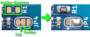
To revert this modification, remove solder bridge on right and add solder bridge on left of JP4.
| Key | Type | Unit | Range | Default |
|---|---|---|---|---|
| vm_volt_comp | Bool | - | - | false |
Back EMF Low Slope Compensation (Voltage Mode)
How much to adjust the voltage to compensate for Back EMF during slow speed operation on acceleration and deceleration phases.
| Key | Type | Unit | Range | Default |
|---|---|---|---|---|
| vm_bemf_slopel | Float | % | 0 - 0.4 | 0.0375 |
Back EMF Slope Changeover Speed (Voltage Mode)
At which speed to change over between slow and fast speed Back EMF slope compensation.
| Key | Type | Unit | Range | Default |
|---|---|---|---|---|
| vm_bemf_speedco | Float | steps/s | 0 - 976.5 | 61.5072 |
Back EMF High Slope Acceleration Compensation (Voltage Mode)
How much to adjust the voltage to compensate for Back EMF during fast speed operation on acceleration phase.
| Key | Type | Unit | Range | Default |
|---|---|---|---|---|
| vm_bemf_slopehacc | Float | % | 0 - 0.4 | 0.0615 |
Back EMF High Slope Deceleration Compensation (Voltage Mode)
How much to adjust the voltage to compensate for Back EMF during fast speed operation on deceleration phase.
| Key | Type | Unit | Range | Default |
|---|---|---|---|---|
| vm_bemf_slopehdec | Float | % | 0 - 0.4 | 0.0615 |